Network maps
Network Maps are a graphical representation of the network to be monitored. Network maps can be accessed through the menu on the left in the Operation → Topology Maps → Network Map.
Network map items
Network maps may contain:
Real nodes
They represent the Agents added on the map. These nodes have an icon representing the Agent's operating system and a halo of the Agent's status. The default shape is circular and other shapes can be chosen. The status represented in the node can be:
- Green : It is in the correct state.
- Red : One of your Modules is in critical condition.
- Yellow : You are in a warning status for one of your Modules.
- Orange : One of the alerts was triggered in the Agent.
- Grey : The Agent is in unknown status.
Fictitious nodes
They represent a link to another Network Map or just a point for personal use within the map. They may have any of the available shapes (circle, diamond, square), any size and label. If it is a link to another map, the color of the node follows the same rules as the real Nodes (colors can be customized).
Lines of kinship between nodes
Kinship lines can be of two types:
- Simple kinship lines (parent-child relationship), which represent the hierarchy of the network map components.
- Network interface relationship lines, which represent the connection of the map components through their network interfaces. These lines are characterized because they end or start with round arrowheads, which represent by means of a color the state of the network interface. In order to establish this type of relationship, it is necessary for the agent represented by the node to have the
ifOperStatusmonitoring modules of its network interfaces, which, in addition, must have the nomenclatureifname_ifOperStatus(for example,eth0_ifOperStatus). This allows you to easily locate the interfaces of the network map elements by name.
Creation of a new Network Map
Empty network map
When using the Create empty network map option, a form emerges, in which you must indicate the name, group and description of the Network Map, along with the radius of the nodes in it. Clicking the Save network map button will create the new Network Map, in which you may start adding elements.
Non-empty network map
This form has the same options as above with a few additional ones:
- Position X: Shift applied to the default position on the map to display it always the same on the horizontal axis component.
- Position Y: Shift applied to the default position on the map to display it always the same on the vertical axis component.
- Zoom scale: Magnification applicable to the default view of the map to display it always with this same factor.
- Source: Filter or Agent source from which the map will be generated or new nodes will be added to holding area.
- The options are:
- Group: Only the agents that belong to that group or child groups appear in the Networkmap (or holding area). Even if the user who is creating the network map does not explicitly belong to the ALL group, user can still assign the ALL group as an Agent source.
- Recon task: Only agents that have been discovered by the recon task chosen in the same form appear in the Networkmap (or in the holding area). The recon task will be in charge of including new nodes to the network map when it is executed.
- CIDR IP mask: Only agents whose main IP address passes the IP mask filter appear in the Networkmap (or in the holding area):
- Source group: List of groups from which the agents of the environment will be searched to represent on the map.
- Don't show subgroups: Option to exclude agents from child groups of the selected ones.
- Source from recon task: Network discovery task from which the map nodes will be updated.
- CIDR IP mask: Network address from which the agents of the environment to be represented on the map will be searched.
- Network map creation method: The method of distribution of the nodes that will make up the network map.
- Options:
- Radial dynamic: The map will consist of a series of concentric circles representing the map nodes with their states.
- Spring: The map will arrange the nodes in a tree-like distribution.
- Refresh: Refresh time of the network map display.
Network map generation options cannot be edited once the map has been created: Source, Source group, Source from recon task, CIDR IP mask, Network map creation method.
After defining the necessary options, click Save network map to save. From that moment, Pandora FMS Web Console will start to generate the network map and redirect to it.
Network map as a favorite element
Version 770 or later.
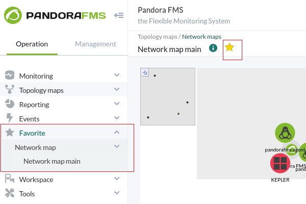
After creating a network map, either empty or non-empty, in the main view of the network map you may check it as a favorite by clicking on the star icon next to the network map name.
To remove it from favorites, just uncheck it by clicking on the star icon again. All the network maps that are checked as favorites will be marked in section Network map from the menu Favorite (Operation section).
Editing a network map
To access the edition of a Network Map, click on the corresponding edit button. The network map editing form is exactly the same as the creation form, except that some fields are disabled because the network map has already been generated. Once the changes have been made, click Update network map to save.
Duplication of a network map
From the list of Network Maps, it is possible to duplicate a Network Map with all its contents and all its settings. The new Network Map will be named as Copy of….
View of a network map
When viewing a created Network Map, its different fields are displayed and it is possible to configure its existing nodes.
Minimap
The Minimap provides a global, reduced view of the whole map extent. In addition, a red box representing the section of the map being displayed on the screen is shown in the upper left corner. It can be hidden by clicking on the arrow icon.
Context menu
From the context menu you may perform some tasks on the Network Map. It is possible to display it by right-clicking anywhere without map elements.
Holding area
New network nodes appear here, avoiding confusingly appearing new nodes in the middle of your network maps and reflecting the changes of the monitored architecture in a clear way.
New nodes appear only when refreshing through the context menu. In addition, the Network Map creation filter is applied to search for new nodes, e.g. by group, by netmask or other new nodes found by a network recognition task. The nodes remain there until they are dragged out.
Editing nodes
Change position
To select, click on the node and then with another click, keeping the mouse pressed, drag the node to be moved on the map.
Relate one node to another
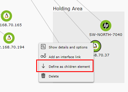
Clicking on a node with the right mouse button brings up a context menu. Choose the option Define as children element.
This starts the linking operation. To complete it, right-click on another node and in the context menu that appears, accept the option Define as parent element to finish linking or you may cancel the operation with the option Abort the action of set relationship.
At the end of the operation, both nodes will be linked.
It is also possible to define from the context menu a type of relationship by network interface, being able to select from which network interface the connection is made.
In the same way as in the previous case, the link can be made by primary clicking on the element that will be defined as a child and choosing the option Add an interface link.
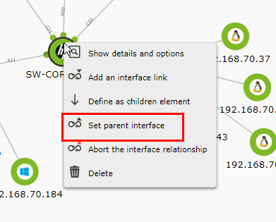
Then right-click on the parent node and choose the Set parent interface option from the context menu (as in the previous case, you may cancel the relationship by clicking on Abort the interface relationship).
A window will then appear asking you to select the interface to be used on both nodes for the link.
Once the interfaces are selected in both nodes, a circle will appear right at the ends of the link representing the status of these interfaces (status of the ifOperStatus Module of the interface).
View node information
Right-click on one of them and choose Show details and options from the menu.
Delete nodes
Change the shape of the state halo
Accessing the node information window, section Node Options, the desired figure is chosen (Circle, Rhombus, Square). Click on the Update node button to save the changes.
Delete relationships between nodes
Accessing the Agent information, section Relationships, select the interfaces in the Interface Source column for each node and delete the link.
Mass node editing
You may select multiple nodes in the following ways:
- Hold down the
Ctrlkey, clicking one at a time on the nodes to be edited. - Right-click on an empty area and drag and drop to select a specific area containing the nodes.
Once several nodes have been selected, they will appear with a darker black border to differentiate them from those that are not selected, and with them you may perform the following mass operations:
- With the main mouse button, drag them all at the same time.
- With the right mouse button, display a menu in which you may perform actions such as linking by parentage to another node, adding a link to another interface, opening the details and options window, or deleting nodes.
If you open the details and options window, you will be able to see information about the node, the interface, the relationships with other nodes and also the option to change the shape of the status halo (in the case of a fictitious node, change the shape of the node).
Agent node creation
Click on a blank area of the generated Network Map and choose option Add node.
Unique creation of a node
In the context menu, in the add Agent section, there is an intelligent control that filters and displays the list of possible Agents according to the request. Once chosen, click Add Agent node to create the new node on the map.
Mass node creation
From the second section of the Add Agents menu, Add Agent Node (Filter by group), you may add multiple Agent nodes by filtering by a group. Select the desired agents from the Agents box and click Add Agent Node.
Creation of fictitious nodes
From the third section of the add agent menu, Add fictional point, you may add fictional nodes. Specify the name of the new fictional node, point to the Network Map it links to (if it links to one) and click Add Fictional Node.
Modify zoom level
With the mouse wheel you may change the zoom in or zoom out level on the network map to see a map section in more detail. In total there are 5 zoom levels.


 Home
Home


